A thermal break is checked by building a two-dimensional model of the frame section, applying the standard's boundary conditions, and reading the heat flux across it. The result depends as much on the cut line and the conditions as on the break.
How to model or check a thermal break in a frame
rev Cissue 04rev Crots yes — the figures above move with the standarddrawn by The Transom Set (a named set, not a person)
The set-up decides the answer
The surface heat transfer coefficients are fixed by the standard, not chosen: the internal and external films have values that the standard prints, and using a different pair changes the result by more than a small break does. The cut line has to be far enough from the break that heat flow at the cut is one-dimensional, which usually means 200 mm or more on each side.
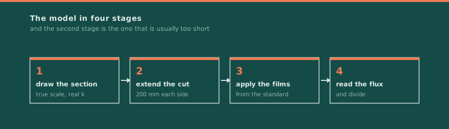
- Draw the section at true scale, with the break material's conductivity, not its name.
- Extend the cut line at least 200 mm each side so the flow at the cut is one-dimensional.
- Apply the surface film coefficients the standard prints, at the standard's temperature difference.
- Read the flux, divide by length and temperature difference, and report the cut line with the figure.
What the number includes
A frame U-value is not the U-value of the break. It includes the aluminium either side, the glazing rebate, the gasket and the spacer, and it changes when the glass unit changes. That is why a frame figure quoted without the glass build-up it was modelled with is a figure about a different window.
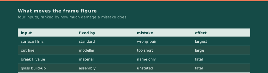
| Input | Fixed by | If it changes | Effect |
|---|---|---|---|
| surface films | the standard | wrong pair used | larger than the break |
| cut line length | the modeller | too short | flux reads high |
| break conductivity | the material | name used instead | result meaningless |
| glass build-up | the assembly | not stated | figure describes another window |
A simulated frame U-value is not a tested one. The simulation is a good predictor when the inputs are right and the cut line is long enough, and it cannot detect a manufacturing defect in the break itself.
Where this sheet stops
This page covers the check. The break itself is owned by the thermal break page, the section it sits in by the mullion page, and the debond failure by the revision on that subject.
Documents this sheet is drawn from
- 1THERM 8.0 Program Description and User Manual (LBNL)supports the two-dimensional heat transfer simulation approach and its set-up
- 2WINDOW - Documentation (LBNL Windows & Daylighting)supports the window modelling documentation the frame figures are produced with
- 3Window Software Downloads (LBNL WINDOW / THERM)supports the software distribution used to produce and verify the model
Each line points at one specific document, with its own title as the link text. No line is a home page and no line is a search result.
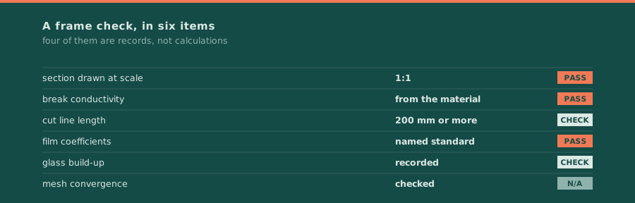
Sign the sheet and stop Sign the sheet and stop once the cut line, the films and the glass build-up are all recorded. Without those three the figure is not reproducible.